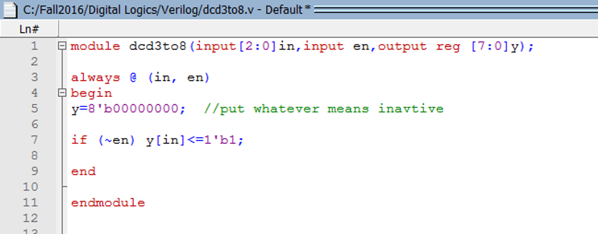
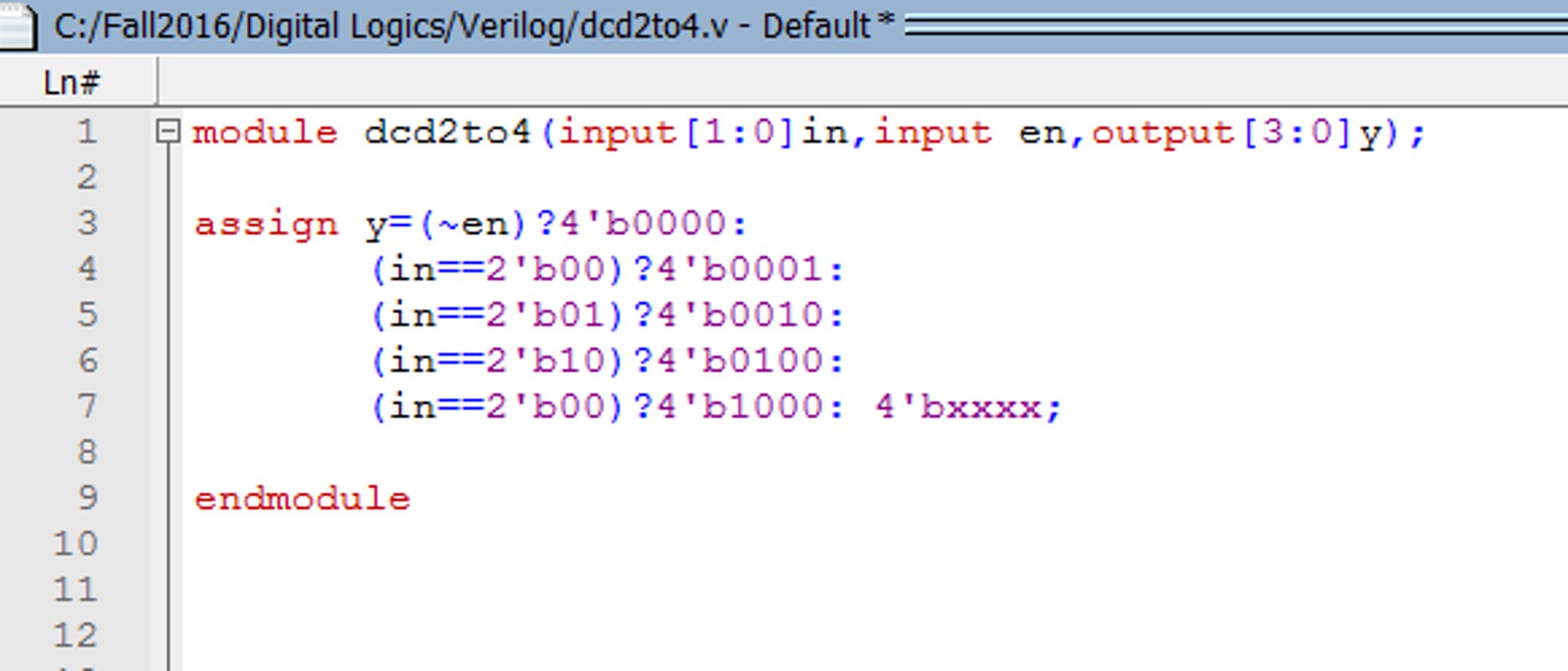
Designing of 2 to 4 Line Decoder Circuit. Similar to the multiplexer circuit, the decoder is not restricted to a particular address line, and thus can have more than two outputs (with two, three, or four address lines). The decoder circuit can decode a 2, 3, or 4-bit binary number, or can decode up to 4, 8, or 16. Browse other questions tagged verilog xilinx decoder modelsim or ask your own question. The Overflow Blog Podcast 353: Bring your own stack – why developer platforms are going headless. In Verilog Coding, of a particular combinational circuit it is necessary to know the number of input/output a particular chip may require. Since, we now understand the concept behind the decoder, we should start with the logic oriented part. Any digital circuit can be realized using Truth Table. Designing of 2 to 4 Line Decoder Circuit. Similar to the multiplexer circuit, the decoder is not restricted to a particular address line, and thus can have more than two outputs (with two, three, or four address lines). The decoder circuit can decode a 2, 3, or 4-bit binary number, or can decode up to 4, 8, or 16 time-multiplexed signals.
- 4 To 16 Decoder Using 2 To 4 Decoder Verilog Code Using
- 4 To 16 Decoder Using 2 To 4 Decoder Verilog Code
4 To 16 Decoder Using 2 To 4 Decoder Verilog Code Using


4 To 16 Decoder Using 2 To 4 Decoder Verilog Code
module decrd_2_to_4(
input [0:1] X,
output [0:3] Y
);
wire w1,w2;
not A0(w1,X[0]);
not A1(w2,X[1]);
and AN0(w1,w2,Y[0]);
and AN1(w1,X[1],Y[1]);
and AN2(X[0],w2,Y[2]);
and AN3(X[0],X[1],Y[3]);
endmodule
//Test Module
module test_decrd_2_to_4;
// Inputs
reg [0:1] X;
// Outputs
wire [0:3] Y;
// Instantiate the Unit Under Test (UUT)
decrd_2_to_4 uut (
.X(X),
.Y(Y)
);
initial begin
// Initialize Inputs
X = 0;
// Wait 100 ns for global reset to finish
#100;
// Add stimulus here
#50 X[0]=0;
X[1]=1;
#50 X[0]=1;
X[1]=0;
#50 X[0]=1;
X[1]=1;
end
initial begin
$display(' x0 x1 B0 B1 B2 B3n');
$monitor(' %d %d %d %d %d
%dn',X[0],X[1],Y[0],Y[1],Y[2],Y[3]);
end
endmodule